
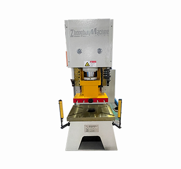
Hydraulic Press Machine, Model No.: Y21-80T
2.the main structure and use of the machine tool:
1. The whole machine adopts the whole steel plate welding structure, the stress is eliminated by vibration, and the accuracy is good.
2. Adopt advanced integrated hydraulic system, good reliability.
3. When stamping products, you can feed from the front, left and right sides of the press. The slider can be used for single stroke and continuous stroke.
3.1 Fuselage
The fuselage is welded from steel plates, and the fuselage work table has square and round blanking holes to drop out products or wastes. The body work table is equipped with a work table, and the work table and the work table are provided with a T-shaped groove for installing the mold. The slide block moves in the left and right guide rails fastened to the fuselage. The slide block is spherical connected with the cylinder piston and moves up and down along the fuselage guide rail by relying on the slide block guide rail. The surface of the slide block and the workbench is provided with a "T" groove for fastening the installation mold.
3.2 Oil Cylinder
The cylinder body and piston rod of the hydraulic cylinder of the hydraulic press are made of high quality materials and are professionally manufactured. The surface of the piston rod has undergone strict heat treatment, and the hardness of the guide part is about HRC45. The main seal of the cylinder adopts a new type of sealing ring with low friction resistance and high pressure resistance. The movement guide of the piston rod adopts a non-metal wear-resisting ring with strong bearing capacity to avoid the cylinder pulling phenomenon that may be caused by metal contact. The cylinder body is fastened in the center hole on the fuselage by the cylinder shoulder, the lower end of the piston rod is connected with the ball of the slider, the cylinder guide sleeve is used for guiding, the piston head is equipped with the opposite direction of the hole sealing ring, forming two oil chambers in the cylinder, the cylinder guide sleeve part is also equipped with the shaft sealing ring with the flange to lock to ensure the seal of the lower chamber, the cylinder tail large hole is installed in the filling valve.
3.3 Liquid Charging system
The filling system consists of a filling valve and a filling cylinder.
When the slider goes down quickly, the main valve of the filling valve is sucked open due to the negative pressure of the upper chamber of the main cylinder, so that a large amount of oil in the filling cylinder flows into the upper chamber of the master cylinder, so that the slider can go down smoothly and quickly. When relieving pressure,
The control oil first enters the control valve, so that the control piston overcomes the spring force and pushes the unloading valve core down, so that the high pressure oil in the upper chamber of the master cylinder is connected to the liquid filling cylinder through the unloading valve core, and the pressure relief goal is achieved.
A long oil mark is arranged on the upper part of the liquid filling cylinder to observe the oil level. The overflow pipe of the liquid filling cylinder 踣 divides the volume of the liquid filling cylinder into two parts: the lower oil is for the rapid downward use of the slide block, and the upper volume is to accommodate the oil discharged from the upper chamber of the master cylinder when the slide block returns. In the lower side of the filling cylinder, a brake valve is provided for regular replacement of the oil.
The filling valve is securely connected to the bottom of the cylinder with the thread on the seat and is sealed with an O-ring. The filling cylinder is connected by the middle plane and the upper end of the master cylinder, and is fastened by bolts and sealed with oil-resistant rubber pads. The cover of the cylinder is provided with a vent hole, and the liquid filling cylinder is provided with a hook.
3.4 Power Mechanism
The power mechanism is made up of fuel tanks. High pressure oil pump, motor, integrated valve block, etc. It is the mechanism that generates and distributes the working oil so that the main engine can complete the predetermined actions.
The hydraulic system is composed of energy conversion device (motor, pump and cylinder, etc.) energy regulating device (various valves) and energy conveying device (fuel tank, pipeline), etc. By means of the control of the electrical system, the slider and ejector cylinder are driven to complete various process action cycles. The working performance and parameters of each part of the system have been strictly tested and adjusted before leaving the factory, and the user only needs to adjust the pressure control valve during use
(0-25Mpa), other may not be adjusted or changed without authorization.

 Spain
Spain Arab
Arab Portugal
 whatsapp
 skype
skype E-mail
 Inquiry